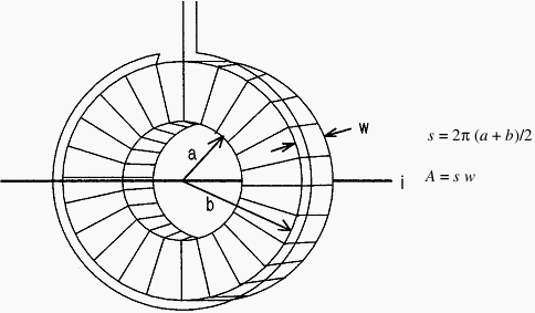
Figure 1 shows the construction of a Rogowski coil, an air-core current transformer that is especially well suited to measuring ripple currents in the presence of a DC component or measuring pulsed currents.
The raw output is proportional to the derivative of the current, and the current can be recovered by an integrator or a low-pass filter.
The output voltage is given by:


Figure 1 - Rogowski coil construction
Where:
n is the number of turns
A is the cross sectional area of the toroid
s is the centerline circumference
A is the cross sectional area of the toroid
s is the centerline circumference
The coil is wound on an air-core form of suitable size for the current conductor. The winding should be applied in evenly spaced turns in one direction only-not back and forth-so that capacitive effects are minimized.
The far end of the winding should be brought back around the circumference of the coil to eliminate the turn formed by the winding itself. The winding must generally be shielded, since the output voltage is relatively low. The shield should be applied so that it does not form a shorted turn through the opening, and the coil should be equipped with an integral shielded output lead with the ground side connected to the coil shield.
Output from the Rogowski coil can either be integrated with a passive network as an R/C low-pass filter or with an operational amplifier.
The advantage of the R/C network is that no power is required for operation. The disadvantages are that it cannot be gated and that the output voltage becomes very low if low-frequency response is required.
Although a toroidal form is shown in the sketch, Rogowski coils are commercially available that are wound in the form of a very long, flexible solenoid that can be wrapped around a conductor and then secured mechanically.
Rogowski coils are largely unaffected by stray fields that have a constant amplitude across the coil. A field gradient across the coil, however, will introduce a spurious output if the field is time varying.
It is good practice to make the coil as small as possible within the electrical and physical constraints of the equipment.
The Rogowski coil can be calibrated from a 50/60-Hz current assuming, of course, that the bandpass of the filter or integrator extends down to those frequencies.
No comments:
Post a Comment