Solutions for powerline, wireless, and serial communications (Maxim, www.maxim-ic.com/communications)
Overview
An electricity grid without adequate communications is simply a power “broadcaster.” It is through the addition of two-way communications that the power grid is made “smart.”
Smart grid communications enables utilities to achieve three key objectives: intelligent monitoring, security, and load balancing. Using two-way communications, data can be collected from sensors and meters located throughout the grid and transmitted directly to the grid operator’s control room. This added communications capability provides enough bandwidth for the control room operator to actively manage the grid.
The communications must be reliable, secure, and low cost. The sheer scale of the electrical grid network makes cost a critical consideration when implementing a communications technology. Selecting a solution that minimizes the number of modems and concentrators needed to cover the entire system can dramatically reduce infrastructure costs.
At the same time, the selected technology must have enough bandwidth to handle all data traffic being sent in both directions over the grid network.
Communications networks and protocols
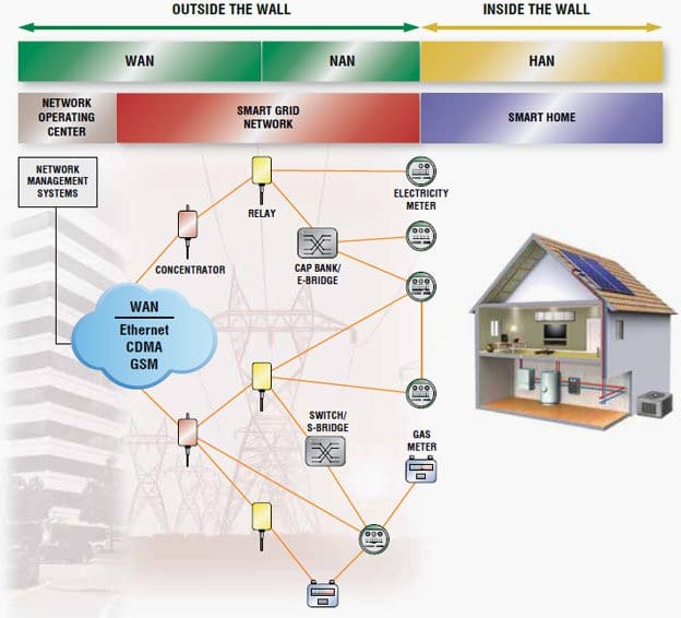
Communications in the smart grid can be broken into three segments:
Wide area network (WAN)
It covers long-haul distances from the command center to local neighborhoods downstream.
Neighborhood area network (NAN)
It manages all information between the WAN and the home area network using medium-voltage lines.
Home area network (HAN)
It extends communication to endpoints within the end-user home or business.
Each segment is interconnected through a node or gateway: a concentrator between the WAN and NAN and an e-meter between the NAN and HAN. Each of these nodes communicates through the network with adjacent nodes. The concentrator aggregates the data from the meters and sends that information to the grid operator.
The e-meter collects the power-usage data of the home or business by communicating with the home network gateway or functioning as the gateway itself.

The smart grid communications architecture
Each segment can utilize different communications technologies and protocols depending on the transmission environments and amount of data being transmitted. In addition to the architecture choice between wireless and powerline communications (PLC), there are a variety of wireless and PLC protocols to choose among (Table 1).
| Network | Protocol | Advantages | Disadvantages | Recommendation |
| WAN | Wireless (2G/3G/LTE cellular, GPRS) | Extensive cellular infrastructure is readily available; large amount of aggregated data can be communicated over a long haul | Utility must rent the infrastructure from a cellular carrier for a monthly access fee; utility does not own infrastructure | Wireless usually works best |
| HAN | Wireless ISM | Long range; leaps transformers | Currently proprietary; dead spots complicate installation and maintenance | Useful in some topologies, such as in the U.S. |
| IEEE® 802.15.4g | Long range; leaps transformers | Not yet an accepted standard | Useful in some topologies | |
| ZigBee® | Low cost; low power consumption allows battery operation; well-known standard | Low data rate; very short range; does not penetrate structures well | Unlikely to be used in NANs | |
| First generation PLC (FSK, Yitran, Echelon®) | Low cost | Unreliable; low bandwidth | Bandwidth and reliability inadequate for the smart grid | |
| Early generation narrowband OFDM | Better range, bandwidth, and reliability than FSK | Does not cross transformers; does not coexist with first-generation PLC | Not recommended for new designs due to cost and compatibility concerns | |
| Broadband PLC | High data rate | Does not cross transformers | Increases infrastructure cost, making it too costly for most large-scale deployments | |
| G3-PLC | Highly reliable long-range transmission; crosses transformers, reducing infrastructure costs; data rate supports frequent two-way communications; coexists with FSK; open standard; supports IPv6 | Not yet an accepted standard | Excellent for NAN worldwide | |
| HAN | ZigBee | Well-known standard that offers low cost and low power | Very short range; does not penetrate structures well | Well suited for communication between water and gas meters |
| Wi-Fi® | Popular technology with high data rates | Medium range; does not penetrate cement buildings or basements | Good for consumer applications, but no provisions for meeting utility objectives | |
| First-generation PLC (FSK, Yitran, Echelon) | Low cost | Not reliable in home environments | Unlikely to be used in homes due to high levels of interference | |
| Early generation narrowband OFDM | Better range, bandwidth, and reliability than FSK | Does not cross transformers; does not coexist with first-generation PLC | Not recommended for new designs due to cost and compatibility concerns | |
| Broadband PLC | High bandwidth | Short range is not sufficient for NAN | Good for consumer applications, but no provisions for meeting utility objectives | |
| G3-PLC | Highly reliable; sufficient data rate; IPv6 enables networking with many devices | Not yet an accepted standard | Excellent for HAN worldwide |
The WAN is the communications path between the grid operator and the concentrator. The WAN can be implemented over fiber or wireless media using Ethernet or cellular protocols, respectively.
Cellular or WiMAX® is most commonly used between the grid operator and the concentrator. The NAN is the path between the concentrator and the meter. It uses either wireless or PLC. Typically, the concentrator communicates with anywhere from a few to hundreds of meters, depending on the grid topology and the communications protocol used.
Today, there is no standard for this portion of the network, so most implementations use proprietary wireless or PLC technologies. Several standards bodies are currently working with utilities and technology providers to define standards for wireless and PLC protocols.
The IEEE 802.15.4g standard targets wireless; the IEEE P1901, OPEN meter, and ITU-T G.hnem standards are being developed for PLC (Table 2).
| Region | WAN | NAN | HAN |
| North America | Cellular, WiMAX | G3-PLC, HomePlug®, IEEE 802.15.4g, IEEE P1901, ITU-T G.hnem, proprietary wireless, Wi-Fi | G3-PLC, HomePlug, ITU-T G.hn, Wi-Fi, ZigBee, Z-Wave |
| Europe | Cellular | G3-PLC, IEEE P1901, ITU-T G.hnem, PRIME, Wi-Fi | G3-PLC, HomePlug, ITU-T G.hn, Wi-Fi, Wireless M-Bus, ZigBee |
| China | Cellular, band translated WiMAX | G3-PLC, RS-485, wireless to be determined | G3-PLC, RS-485, Wi-Fi, to be determined |
| Rest of the World | Cellular, WiMAX | G3-PLC, HomePlug, IEEE 802.15.4g, IEEE P1901, ITU-T G.hnem, PRIME, RS-485, Wi-Fi | G3-PLC, HomePlug, ITU-T G.hn, RS-485, Wi-Fi, Wireless M-Bus, ZigBee, Z-Wave |
The HAN is used by utilities to extend the reach of their communication path to devices inside the home. This network can support functions such as cycling air conditioners off during peak load conditions, sharing consumption data with in-home displays, or enabling a card-activated prepayment scheme.
The arrival of electric/plug-in hybrid electric vehicles (EV/PHEVs) presents a special communications scenario for HANs.
Standards bodies are defining PLC protocols for communicating with vehicle charging systems. In addition to supporting the data requirements for smart grid activities, a HAN might also include: peer-to-peer (P2P) communications between devices inside the home; communications with handheld remote-control devices, lighting controls, and gas or water meters; as well as broadband traffic.
Protocols such as RS-485, ZigBee, Z-Wave®, and HomePlug are used for this network. If there is a separate home gateway, it is possible that additional protocols could be used to communicate with appliances, thermostats, and other devices.
Communications alternatives in the HAN can often coexist, but utility support will probably be limited to technologies needed to support the utility’s primary objectives.
Resource: Maxim (solutions for powerline, wireless, and serial communications); www.maxim-ic.com/communications


